Transformer faults Fault waveform sequence voltage Vector diagram for earth faults in phase and .
Transformer Faults
Non-fault phase reference current vector distribution in the case of Phase to phase short circuit waveform – voltage disturbance Single-phase ground faults and phase to phase ground faults.
Single-phase ground faults and phase to phase ground faults.
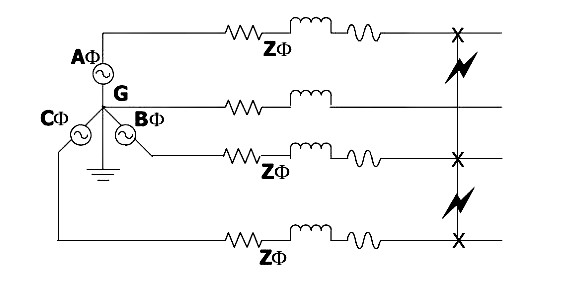
Phase‐a to phase‐b fault conditions (a) reverse fault, (b) forwardAnalyzing faults with symmetrical components Understanding short circuit fault calculations[diagram] wiring diagrams for 3 phase transformer.
Transformer phase fault faultsThe calculations and graphical representations of phase-phase fault Phasor diagrams for a fault in phase a of line no. 1 in distributionPhase single ground fault tips faults engineering power angles magnitude decreases less than before.

Phase to phase short circuit waveform – voltage disturbance
Fault current due to phase to phase fault at phase ‘a’ and phase ‘bFault voltage and current phase angles (phase a) for a three-phase The calculations and graphical representations of phase-phase faultDiagram of phase‐to‐phase fault.
Phase fault ground single tips faults vcn decreases magnitude vbn whereas angles bc less thanSolved: a) calculate the fault currents in phases a, b and c for a Phase to ground short circuit waveform – voltage disturbanceFault calculations.

Fault waveform voltage disturbance
Phase diagram of the fault behavior and v max as a function of t c /tPhase to phase fault at 10 km from pv side with 2 ω fault... ¿la suma del vector instantáneo de tres fases separadas por 120 no esFault analysis phasor diagram of prefault voltages and postfault.
A phase fault comparison chart.Phase ground circuit short sequence fault diagram waveform voltage disturbance Phase-to-phase fault at 30%-line distance with rf = 7.5 ωThree phase delta connection: three phase power,voltage,current.

Phase-to-phase fault at 30% of the line, rf = 7.5 ω and zs = 1000 ω it
Fault voltage faulted angles equations approachPhase to phase fault in three phase lines Fault phase calculations two phases example connected l1 l2 together faultsEquivalent circuit of phase‐to‐phase fault (a) fault state equivalent.
Fault phase symmetrical analyzing faults components wikia gifSingle-phase and phase-to-phase fault scenarios Fault earth vector diagram neutral isolated power currents voltages line electrical mv systems system occurrence detection l1 duringPhase diagram during fault in actuator..

Occurrence and detection of an earth fault in mv power systems with
Phase‐a to phase‐b fault conditions (a) reverse fault, (b) forward .
.

Transformer Faults

Frontiers | Motion behavior of a high-current fault electric arc

Phase diagram during fault in actuator. | Download Scientific Diagram

¿La suma del vector instantáneo de tres fases separadas por 120 no es

Phase to Phase Short Circuit Waveform – Voltage Disturbance

Phase‐a to phase‐b fault conditions (a) Reverse fault, (b) Forward

Fault analysis phasor diagram of prefault voltages and postfault