File bsp2 cw radar en cw radar block diagram continuous wave radar Cw radar transceiver block diagram. Radar systems
File Bsp2 Cw Radar En Cw Radar Block Diagram Continuous Wave Radar
Cw radar block diagram Block diagram of the cw radar system. A block diagram of the proposed cw radar system.
Block diagram of proposed multi-frequency cw radar for small
Continuous radartutorialFmcw radar Fmcw modulatedFig. 3: 24 ghz fmcw radar interface block diagram.
Radar block diagramFrequency modulated continuous wave radar block diagram Radar diagram block system basic transmitter introduction antenna receiver power supply systems facsimile duplexer display typical figureRadar radar: continuous wave radar.

Cw radar proposed
Simple radar circuit diagramsSimple radar circuit diagram What is frequency modulated cw radarBlocks diagram of fm-cw radar system [7].
Radar cw diagram block advantages disadvantages parts velocity equation measured target moving following using receiverIntroduction to radar systems Figure 2 from a comparison of phase-coded cw radar modulation schemesSolved 2. explain the different types of radars based on.

Block diagram of a two‐tone cw doppler radar system. cw, continuous
Pulsed radar system block diagramA block diagram of cw radar system for detecting a chest wall movement Basic radar block diagramRadar cw chest movement detecting.
Radar cw bsp2 continuous pngitem1 simplified block diagram of the digital-if cw doppler radar Circuit diagram of radarAdvantages of cw radar.
/Year_4/ECE 451 L_Radar_Eng_and_Facsimile/Introduction_to_Radar/Images/Radar Block Diagram.PNG)
Fig. 1: 24 ghz fmcw radar module block diagram
Radar doppler cw simplifiedBlock diagram of cw radar system. Simple radar circuit diagramsFmcw radar block diagram..
Difference between long pulse and short pulse radar detectorCw doppler radar block diagram Figure 4 from a comparison of phase-coded cw radar modulation schemes.


Simple Radar Circuit Diagrams - IOT Wiring Diagram

Figure 4 from A comparison of phase-coded CW radar modulation schemes
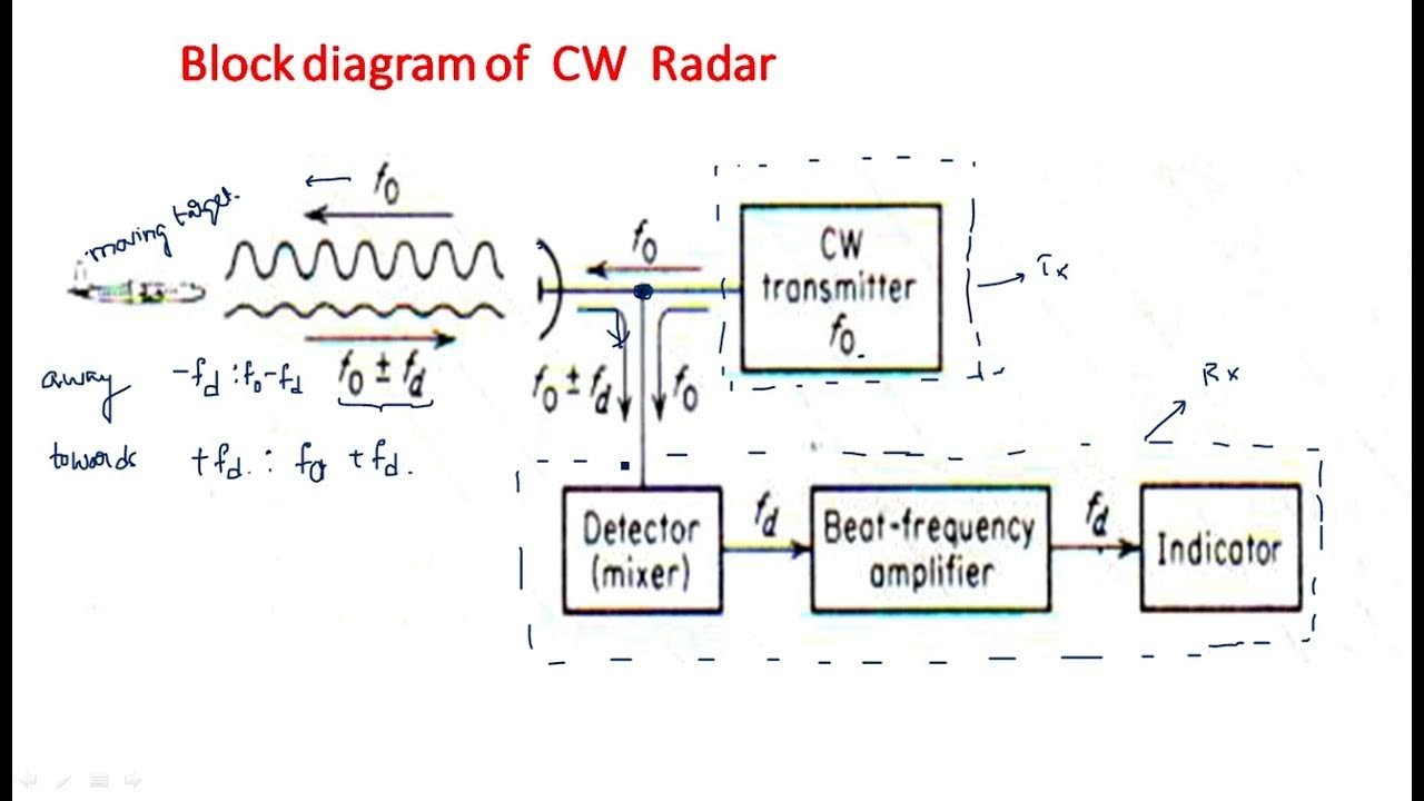
CW Radar block diagram | Continuous Wave | Radar Systems | Lec-19 - YouTube

Block Diagram of proposed Multi-frequency CW radar for small

A block diagram of the proposed CW radar system. | Download Scientific

Radar block diagram | Pulse Radar | PPI Display | Radar Systems | Lec

File Bsp2 Cw Radar En Cw Radar Block Diagram Continuous Wave Radar

Block Diagram of CW radar system. | Download Scientific Diagram